TwinTeeth Plus - Preparing the materials
Bill of materials
You will need the following materials to build the framework:
| SKU | Qty | Material name |
|---|---|---|
| SKUA001 | 1 | Bottom Triangle - 3mm aluminium sheet |
| SKUA002 | 1 | Top Triangle - 3mm aluminium sheet |
| SKU0010 | 3 | Column - 300mm - 15x15mm aluminium extrusion |
| SKU0011 | 3 | Leg - 90mm - 15x15mm extrusion |
| SKU0100 | 1 | Aluminium fixture bed - 70 x 80mm |
| SKU0101 | 1 | Aluminium round tube 20mm dia. x 10mm |
| SKU0102 | 1 | Aluminium stencil - 70 x 80mm |
| SKU0203 | 6 | Half anti-backlash nut |
| SKU0204 | 3 | Springs 6mm(Dh)x4mm(dd) x 15mm(the) - 0.9mm wire -7.85 N/mm |
| SKU0301 | 6 | Glass fibber rod 6x3x136mm |
| SKU0303 | 12 | Hollow rod ends with Balls #5347 |
| SKU0900 | 6 | LM6UU linear bearing |
| SKU0901 | 3 | Trapezoidal threaded rod 200x10mm - 3mm pitch |
| SKU0902 | 6 | Stainless Steel rod - 300x6mm |
| SKU0903 | 6 | Ball Bearing 10x22x6mm F6900ZZ |
| SKU0904 | 3 | Motor coupler 10x5mm |
| SKU0800 | 1 | USB Camera + cable |
| SKU0011 | 3 | Adjustable foot - 15mm (OD) |
| SKU0003 | 1 | DB15 cover |
| SKUA003 | 3 | LeadScrew Top Support |
| SKU0012 | 3 | LeadScrew Top Support Cover |
| SKUA004 | 3 | LeadScrew Bottom Support |
| SKUA005 | 3 | Motor holder |
| SKUA006 | 3 | Retainer Knob |
| SKUA009 | 1 | Marker Pen Hexagon |
| SKU0200 | 3 | Carriage |
| SKU0201 | 3 | Carriage Clamp |
| SKU0300 | 1 | Effector |
| SKU0202 | 2 | Half Nut Mould |
| SKU0801 | 1 | Camera Gimbal set: plate, tulip, hinge, fork |
| SKUM208 | 6 | M2 x 8mm metal-sheet screw (End-stop switches) |
| SKUT214 | 3 | M2 x 14mm plain screw (end-stops adjustment screws) |
| SKUTN02 | 3 | M2 nut |
| SKUT308 | 15 | M3 x 8mm allen screw (DB15, Motors, Camera) |
| SKUT310 | 20 | M3 x 10mm allen screw (DB15, Top Leadscrew Support) |
| SKUT314 | 3 | M3 x 14mm allen screw (Leadscrew adjustment screws) |
| SKUT316 | 9 | M3 x 16mm allen screw (Retainer Knobs, (Carriages) |
| SKUT318 | 9 | M3 x 18mm allen screw (Effector) |
| SKUT320 | 1 | M3 x 20mm allen screw (Camera) |
| SKUT325 | 1 | M3 x 25mm allen screw (Camera) |
| SKUT330 | 6 | M3 x 30mm allen screw (Carriage springs) |
| SKUC310 | 2 | M3 x 10mm counter sunk screw unpainted (GND, Spring telephone cable) |
| SKUC325 | 16 | M3 x 25mm counter sunk screw (Arduino, Motor holders) |
| SKU0302 | 12 | M3 x 10mm threaded rod |
| SKUTN03 | 4 | M3 Nylon nut (Arduino) |
| SKUTY03 | 7 | M3 Nylock nut |
| SKUTN03 | 61 | M3 nut |
| SKUTW03 | 8 | M3 washer |
| SKUTNU2 | 24 | M4 x 4mm grub screw (T-nuts) |
| SKUTNU1 | 6 | M4 Double T-Nut |
| SKUC416 | 21 | M4 x 16mm counter sunk screw (columns and rods) |
| SKU0105 | 8 | 2.5 x 8mm precision dowel pin |
| SKU0106 | 8 | 2.5 x 10mm precision dowel pin |
| SKUE001 | 1 | Male DB15 Connector 2 rows |
| SKUE003 | 4 | M3 x 10mm plastic PCB spacer |
| SKUE002 | 3 | DB1 size microswitch without flange (for endstops) |
| SKUE001 | 2 | M3 Ring terminal connector (GND) |
| SKUE005 | 1 | Alligator Electric Clamp (auto-levelling probe) |
| SKUE006 | 1 | 100nF ceramic capacitor (spring telephone cable) |
| SKUE007 | 1 | 1-Wire male/female connector (spring telephone cable) |
| SKU0104 | 1 | 2.5 x 10mm copper wire (spring telephone cable) |
| SKU1015 | 18 | Zip-tie 2.5x100mm |
| SKU0013 | 3 | 42x42x4mm cork pieces (motor foot) |
| SKUS002 | 1 | Graphite powder bag (10 grams) |
Additionaly you will need the following materials (NOT INCLUDED in the kit) to complete the framework:
| Qty | Material name |
|---|---|
| 1 | Arduino Mega 2560 |
| 1 | Ramps 1.4 with 4 x A4988 Drivers |
| 3 | Stepper motors 42BYGHW609 or similar. Any bipolar motor of 40mm of length and a holding torque between 3.400-4.000 g/cm will do the job. Just take care about max. current consumption because the limit of the drivers is 2A per coil. |
| 1 | Wiring & connectors (see installing the electronics) |
| 1 | PC - ATX power suply with +12V +5V |
| 1 | Epoxy glue |
| 1 | Teflon tape (1 meter) |
Preparing the Aluminium Parts
You will find in the kit two 3mm alu. sheet triangles: the top and the bottom triangle. The top triangle has the hexagonal pocket at the centre.
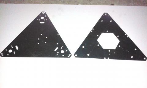
Triangles sides are slightly different. This is the top triangle:

Top side has the countersunk holes.
Bottom triangle has countersunk holes on both sides.
The columns and línear axis countersunk holes identify the bottom side. On the top side you will see the countersunk holes for the motors and the Arduino. In the middle of the triangle you will see a 6mm hole for the fixture bed spring cable.
On next picture you can see the bottom side of bottom triangle. Observe the countersunk holes for the columns and 6mm steel rod linear axis.
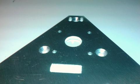
Also take note that the triangle vertexes are slightly different. Z linear axis vertex of both triangles has a pass-through hole for the wiring (see next picture).
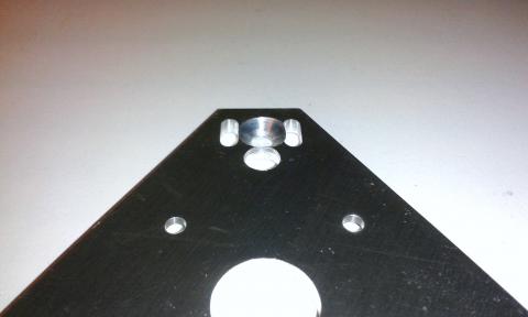
Top triangle Z axis vertex has also two M3 holes for attach the DB15 connector.
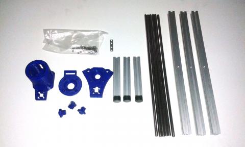
Additionally to the triangles find in the kit the following pieces: plastic parts, 3 x aluminium extrusion columns, 3 x aluminium extrusion legs with adjustable feet, 6 x 6mm stainless steel linear axis, 6 x double tee nuts (to attach columns and legs end-to-end), and 24 x set screws (grub screws) to connect them.
You can see that pieces in the following picture. The plastic parts from left to right are the Motor Holder, the Bottom Lead-Screw Support and the Top Lead-Screw Support. You will find in the kit tree pieces for each. Below those parts you can see the three Toolhead Retainer Knobs.
Before assembling the framework you will need to prepare the materials.
First using a file go inside the three end-stop pockets of bottom triangle and check that the microswitches fit well there.
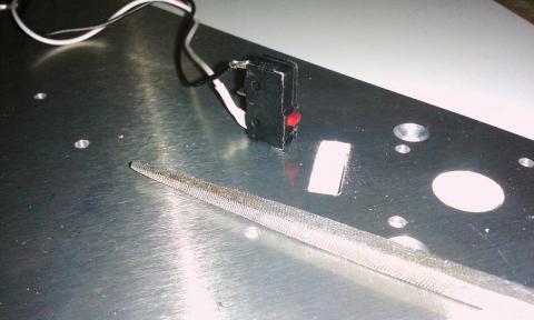
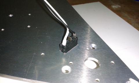
Preparing the Plastic Parts
Now we are going to prepare the plastic parts.
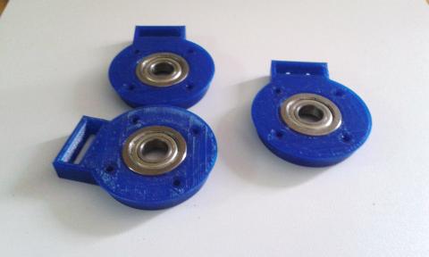
Find a Bottom Lead-Screw Support part and using a M3 drill bit go inside the holes to clear them from debris. Using sandpaper sand a little the wrinkled side.
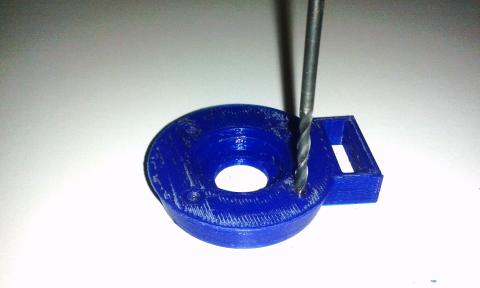
Using a cutter, clear from debris the ball bearing housing and insert a F6900ZZ bearing there.
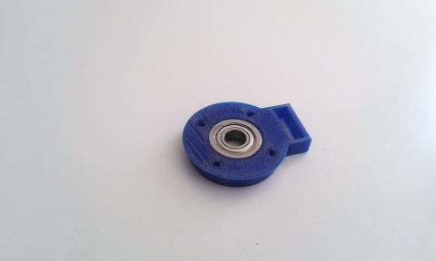
Repeat last steps with each Bottom Lead-Screw Support part.
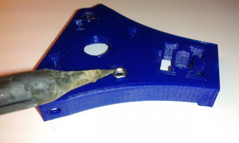
Find a Top Lead-Screw Support part and using a M3 drill bit go inside the holes to clear them from debris. Using a soldering iron, insert 4 x M3 nuts in the traps of the bottom side.
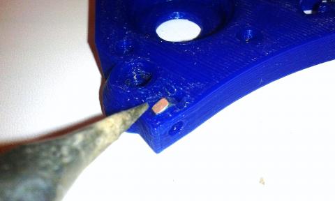
Using also the soldering iron insert one M3 nut in each linear axis retainer
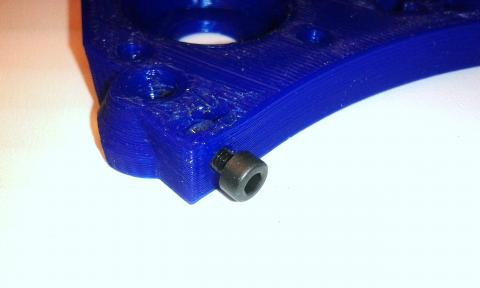
Screw one M3 x 10mm bolt in each linear axis retainer.
Using a cutter, clear of debris the ball bearing housing and insert there a F6900ZZ bearing.
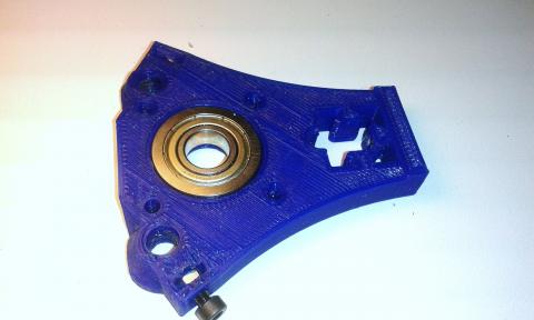
Clean also of debris the aluminium extrusion pocket.
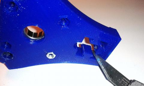
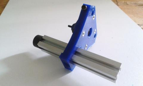
Use one of the legs to check that the aluminium profile slides smoothly through the pocket.
Take a Top Lead-screw Support Cover part and clean also the debris from it.
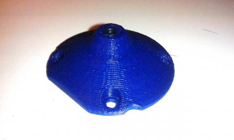
Using the soldering iron, insert a M3 nut inside (see next picture). This is the nut for the lead-screw adjustment bolt.
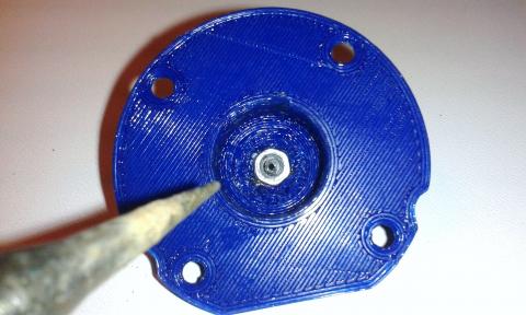
Screw there the M3 adjustment bolt.
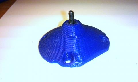
Finally attach the cover to the Top Lead-screw Support part using four M3x10mm bolts.
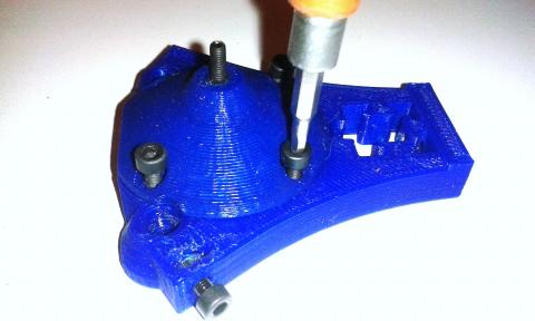
Repeat last steps on each Top Lead-Screw Support part.
Now it's time to prepare the Motor Holder.
Remove with a cutter the remains of support material of the stepper motor housing and extrusion pocket.
Use the cutter to clean blobs, threads and other rest of the 3D printing process.
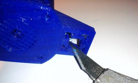
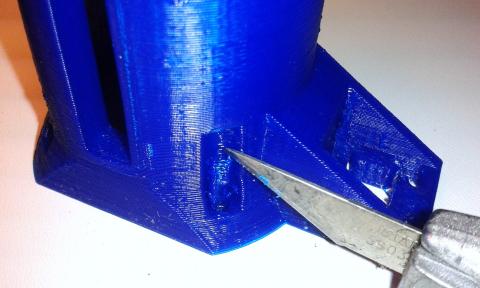
Clean also the motor mounting holes with a M3 drill bit.
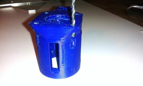
Don't forget the M3 holes on the top side of the part.
Using the soldering iron, insert 4 x M3 nuts in the Motor Holder traps you can see in the picture below. These nuts attach the Motor Holder to the bottom triangle through the holes of the Bottom Lead-Screw Support part.
Tip: once installed the nut, screw a M3 bolt on it to check it screw well and straight. Check also that the nut does not turn in the trap and glue it with a little melted plastic if needed.
Use one of the legs to check that the aluminium profile slides well through the pocket.
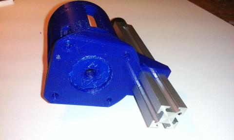
Repeat last steps on each Motor Holder parts.
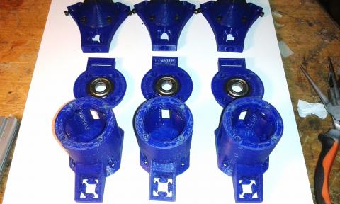
Now you will have the three set of parts ready to be assembled.
Preparing the Nema 17 Motors
Now we are going to prepare and install the Nema 17 motors.
You will need three stepper motors 42BYGHW609 or similar. Any bipolar motor of 40mm of length and a holding torque between 3.400-4.000 g/cm will do the job. Just take care about max. current consumption because the limit of the drivers is 2A per coil.
Glue the motor foot using contact adhesive. It is a piece of cork sheet of 42x42x4mm.
Then attach the motor to the Motor Holder using four M3x8mm screws.
Warning: the motor wires must point out the opposite way of the extrusion pocket (see next picture).
Then you have to install the 5x10 Motor Couplers. Its mission is to connect the motor shaft (5mm D) with the acme lead-screws (10mm D).
Using an M2 Allen key, loose a little the two grub screws which are near to the 5mm-hole side of the coupler.
Put the coupler into the Motor Holder and insert the motor shaft into the 5mm hole of the coupler.
Using a screwdriver move the coupler a little up through one Motor Holder window. The coupler has to stay approx. 5mm from the Motor Holder's bottom surface. Then tighten the bottom grub screws with the Allen key. Tighten them little by little in sequence (in order to centre the coupler with the motor shaft).
Repeat all these steps with the rest of motors.
Preparing the Delta Rods
For prepare the rods you will need: six glass fiber rods, twelve rod-ends with hollow balls and the 12 PCs of M3 x 10mm threaded rod also included in the kit.
First you need to make a jig which helps you to make the six delta rods exactly of the same length. The exact length of the rods is not as important as getting all of the rods the same length because we can adjust it in the firmware later.
You can use a piece of thin plywood, MDF or alu.sheet. We used an alu sheet because metal always provides more precision that wood when drilling.
Drill two holes on the jig exactly at 170mm and thread two M3 x 20mm bolts from the back side of the jig. Thread one M3 nut in the other side of the bolts.
Now you need to Insert the hollow balls into the rod ends' housing. Just push the ball with your fingers until it fits into the hole.
Screw also the M3 x 10mm rods into the tube ends. Probably you will need to make the hole a little bigger because the internal hole of the tubes sometimes is a little irregular. Use a M3 drill bit for that. Then glue the rods inside with a little 5-minutes epoxy. Make sure you leave half of the M3 rod (approx. 5mm) out of the fiber tube and clean the rest of the epoxy glue. Let the epoxy cure.
Once cured, screw two rod ends in the M3 threads and put the delta arm into the jig to check that all the parts fit well together. Then remove it and glue the other side of the M3 thread into the rod ends and put it again on the jig. Adjust the rod ends into the M3 thread till the complete delta rod will be straight from one jig bolt to the other. Make sure that the rod ends are aligned and fit properly in the jig bolts. Remember: the goal is to make six delta rods exactly of the same length.
Repeat the process with the rest of the delta rods.
You will have something like this when you finish the job:
Tip: Hollow balls often have some gap in the plastic housing which could produce backlash in the robot. A tip to solve this issue is to hit a little bit the plastic around the ball using a metal round tube of 5mm ID 6mm OD. I use a piece of tube from an old telescopic antenna. Just hit the plastic a little to deform it, but slightly because you can damage the ball housing. Then check that the ball moves in its housing with less clearance.
Preparing the LM6UU Carriages
The carriages are those parts which move the delta rods and the fixture platform up and down throughout the 6mm steel shafts and lead-screws. They are composed of two parts: the LM6UU Carriage and the Carriage Clamp.
The LM6UU carriage holds the LM6UU linear ball bearing which runs throughout the shafts. They have attached the rod ends of two Delta Rods. In the other side it holds a half-nut. The other half-nut is hold in the Carriage Clamp and the whole is attached together using two M3X30mm bolts, two M3 washers and two springs. See next picture.
Now we are going to prepare the carriages.
First clean the holes with a 3mm drill bit, remove blobs, plastic threads, etc.
Warning: to avoid gaps don't use the drill bit into the bracket holes of the Delta Arms.
Then take one LM6UU linear bearing and check that it fit in the carriage holders. Use a cutter or a file to remove plastic blobs, traces, etc. and test until it fits in the housing. You will see that the plastic housing is flexible and the bearing doesn't fit perfectly on it until your pressure it with your fingers. Don't worry because they will fit in the holdings perfectly when you tigthten the zip-ties later.
Then, using the soldering iron, insert two M3 nuts in their traps (for the clamp bolts) and "glue" them with a little melted plastic.
Screw into its hole the endstop bolt with its nut. This bolt is a tiny 2x14mm plain head bolt. Screw the nut into the bolt and then the bolt oi the plastic hole. This bolt will hit the endstop switch when homing.
Check that the anti-backlash nuts fit well in the back side of the carriage and install: the carriage clamp, the bolts and the springs.
Adjust the nut with a file or sand paper if needed.
Unscrew the bolts, remove the clamp and install the Acme screw on the half-nut of the carriage. Before closing the carriage with the clamp, put a little graphite powder inside the threads of both anti-backlash nuts. Then bolt the system again.
IMPORTANT: to lubricate the nuts and the Acme screws don't use oil or grease, just a little graphite powder (included in the kit).
Picture show the standar springs which are too long (15mm L). Use a wire cutter to cut one in the midle and use the two halfs, one in each bolt of a carriage.
Now, tighten a little the M3 bolts. The springs are strong and if you screw the bolts too much then the carriage will jam and will not move the arms. It has to move smoothly and easily through the lead-screw. If you see that the springs are too long then cut a little the rings till the bolts reach the embed nuts.
Tip: once you have checked that the carriage runs fine and smoothly through the lead-screw, glue with 5-min epoxy one half-nut to the carriage and the other half-nut to the clamp (in their correct positions and without the lead-screw inside). Then bolt both pieces with the M3 screws and springs till the epoxy cures. Take care and avoid to contaminate with the epoxy other pieces like the half-nut threads, bolts, springs, etc. This tip is not strictly needed but it improves the accuracy of the robot. Gluing the nuts to the carriages avoid possible clearances and play between those parts.
Finally insert 4 x zip-tie of 2.5x100mm in the carriage holes to attach (in next chapters) the linear LM6UU ball bearings.
Repeat these steps with the other two carriages.
Preparing the Fixture Bed
Preparing the fixture bed is easy because it comes complete in the kit and almost ready to use.
You will see that the 20mm alu. tube is already installed and glued so you only need to install the connector for the spring cable and bolt it to the back side of the bed.
Bend with pliers the piece of cooper wire (included in the kit) around an unpainted M3 bolt and solder it. Solder also the one-way connector to the wire.
Screw the M3 bolt into the drill of the back side of the bed, just in the centre of the ring and the tube.
Preparing the Effector
The Effector is the plastic part attached to the fixture bed through the 20mm alu. tube and three bolts which clamp that tube. On the other side the Effector is attached to the delta rods.
Now we are going to prepare it.
Remove with the cutter all plastic blobs and threads and clear the holes.
IMPORTANT: in order to avoid gaps, don't use the drill bit into the bracket holes of the Delta Arms.
Check that the fixture bed tube fits perfectly in the Effector 20mm centre hole. Use a cutter or a file to adjust the hole if needed.
Insert with the soldering iron three M3 nuts in their traps. These nuts are for the bolts which will clamp the fixture bed tube.
Then screw on these nuts three M3 x 14mm bolts through the lateral holes of the effector.
When you finish the job, the Effector will look like following picture
At the end of this chapter you will have all the materials prepared and ready for assemble them.
Assembly Index Home Next chapter
