TwinTeeth Plus - Asembling the Framework
Installing the Bottom Triangle
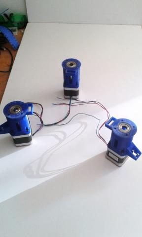
Put the Motor Holders and motors on the table forming a triangle.
Put a Bottom Lead-Screw Support part on each. Take care the micro-switch pocket is pointing to the centre or the triangle and the ball bearing on the top side (see next picture). This will be the motor position on the framework and will help you to assemble the bottom triangle and the rest of parts.
Note that the aluminium extrusion columns have a M4 threaded hole at approx. 155mm from the bottom end. This is important because when installing it on the bottom triangle, the long part of the column must be down with the hole pointing from the centre of the robot to the exterior side (see next picture).
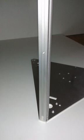
Using a M4 x 16mm countersunk screw, attach one of the columns to one of the bottom triangle vertexes from the bottom side of the triangle.
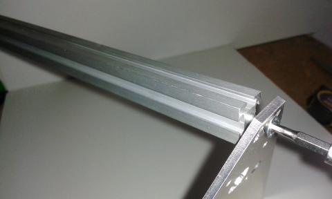
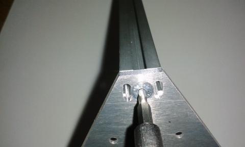
Using M4 x 16mm screws, attach the two 6mm stainless steel linear guides.
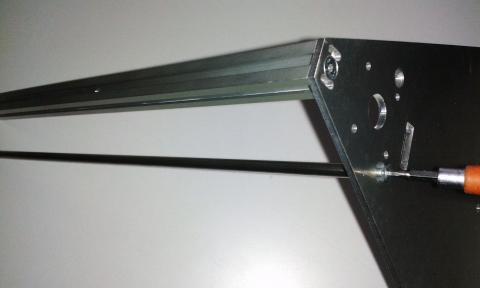
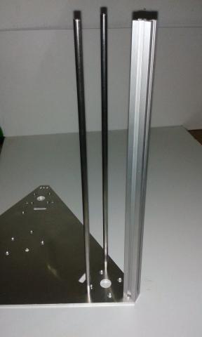
Tighten well the three bolts because you will not be able to do it later: the leg and the motor holder will hide them.
Put the triangle on the Motor Holders. We are going to attach one of them. Do not forget the Bottom Lead-screw Parts.
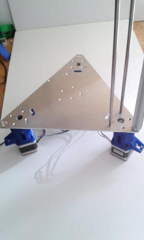
Using four M3 x 25mm countersunk bolts attach the top triangle to a motor holder through the Bottom Lead-screw Support part.
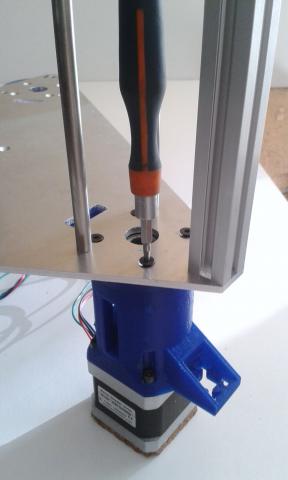
Then you can install the leg.
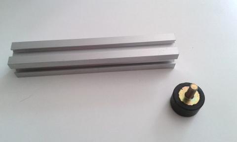
First screw the foot on the bottom end of the leg.
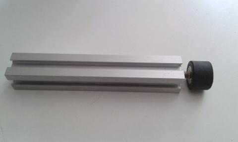
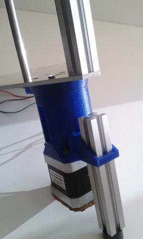
Carefully insert the leg (from the motor side to the triangle side) into the motor extrusion holder.
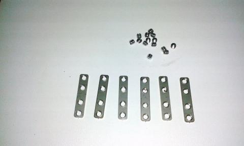
Find the double tee nuts (they attach columns and legs end-to-end) and the set/grub screws to connect them.
Take one T-nut and slide it from bottom to top through the bottom triangle hole and the column extrusion slot. Using two grub screws attach it more or less to the half-length.
Warning: don't tighten too much the grub screws, just enough to avoid the T-nut moves.

Repeat the last step on the other side of the column using another t-nut.
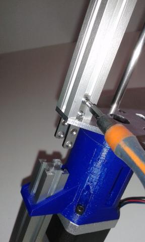
Then carefully slide the leg, inserting the t-nuts in its slots at the same time.
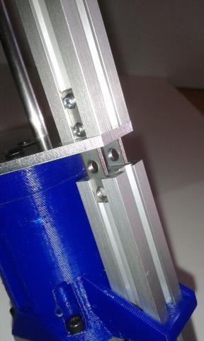
Using your fingers, push the leg against the triangle (to avoid any gap between the triangle and the leg) and using four grub screws attach the T-nut to the leg.
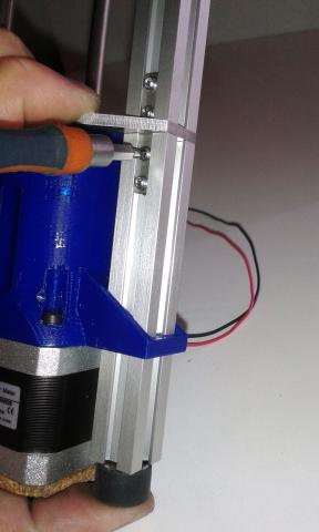
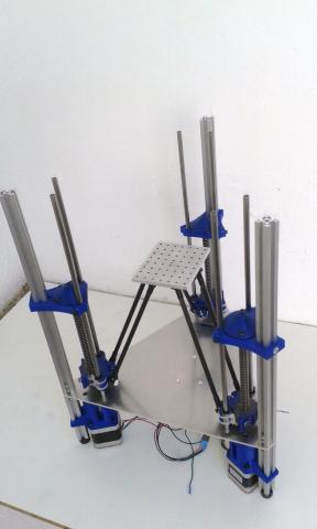
Once the leg is installed, it will look like the following picture.
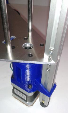
Installing the lead-screw
First, check that the motor coupler grub screws are loosening. Then take one lead-screw and insert it through the ball bearing hole. Finally insert the screw into the motor coupler.
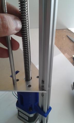
Using a marker pen, paint a mark on the lead-screw screw where it reaches the bottom ball bearings. Then slide up the leads-crew through the ball bearings bringing it out from the motor coupler then apply around the screw some turns of Teflon tape, just below the line you marked. We already described this tip in the plastic version: see Installing the Motion System.
Try to insert again the lead-screw through the ball bearing hole. If it fits without gaps then the job is done. Otherwise, slide it out and put more Teflon tape on it. If you can not insert the screw on the ball bearing, then remove some Teflon tape and try again.
Insert again the lead-crew through the bottom ball bearing and the motor couple and tighten the top grub screws of the motor coupler to attach it.
Then find two LM6UU linear bearing. Put a drop of oil near the top end of the 6mm stainless steel rods and carefully insert the LM6UU linear ball bearing on them.
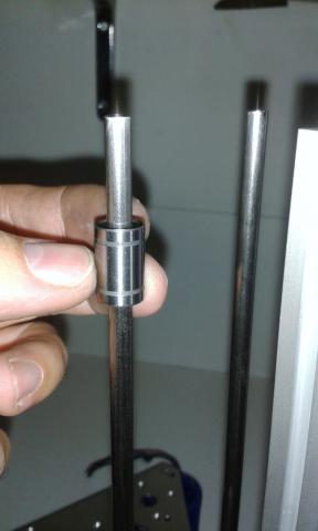
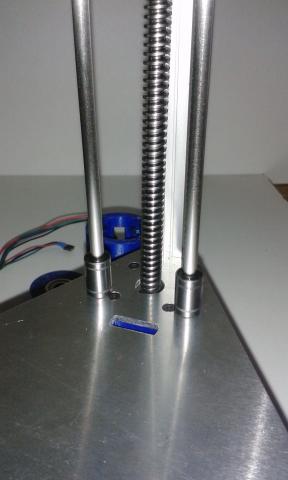
Find a Top Lead-screw Support part and slide it through the aluminum extrusion and the rods till it will reach the top end of the lead-screw. Put some teflon tape around the top lead-screw end, in a similar way you applied it to the bottom end.
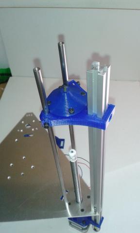
Then using an allen key, screw the adjustment bolt to the middle position.
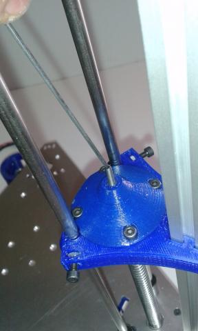
Put a little grease or vaseline on the lead-screw top end for reducing friction with the adjustment screw. Slide down the plastic part a little more until the lead-screw will get inside the ball bearing. It has to touch the adjustment screw tip.
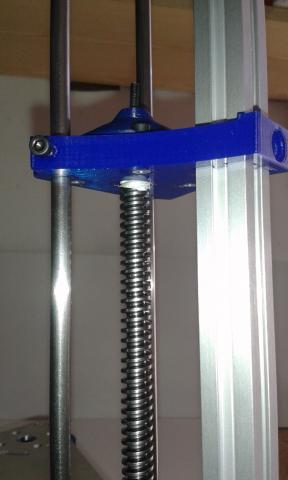
Check that the plastic part hole and the extrusion hole match up. Bolt them together with an M4x16mm countersunk screw.
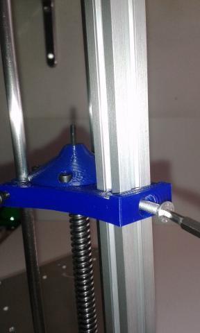
Carefully tighten the steel rod retainer screws.
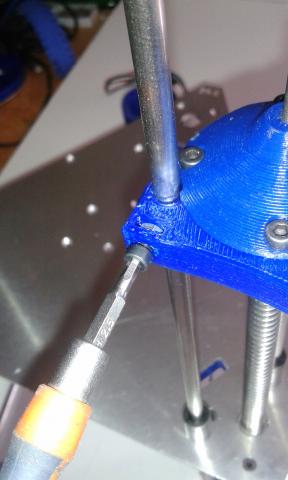
Then, take with your fingers the lead-screw and move it up pushing it against the adjustment screw. Then tighten the motor coupler grub screws of the motor shaft.
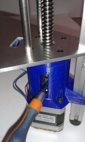
Using your fingers, check that the lead-screw turns smoothly. Move also the lead-screw vertically up and down to check there is just a little vertical gap. Finally turn the adjustment screw to modify the vertical gap if needed.
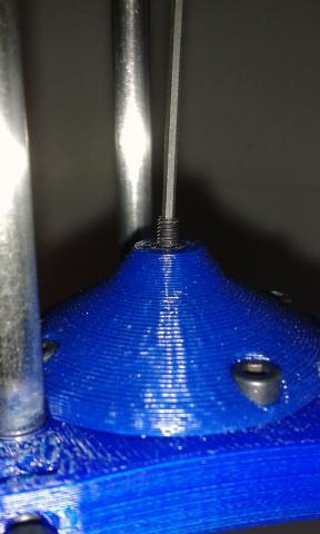
Repeat last steps per each linear axis.
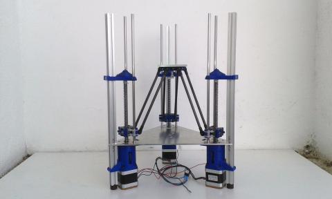
When finish you will have something similar to the following pictures.
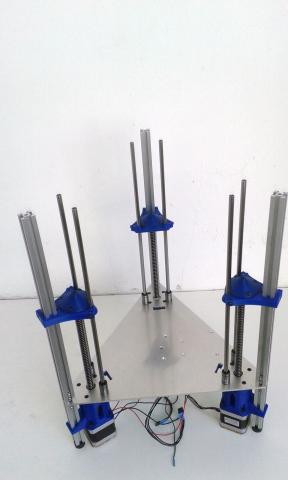
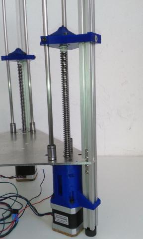
Installing the carriages and the delta motion system
You can install this stuff later, but as the framework is now open on the top side, it is easy to do it now.
The procedure to install them is the same for both printers’ models, so we have recycled some pictures from the original tutorial. You can check the TwinTeeth basic version tutorial here.
First, we are going to install the carriages:
Find the parts needed for one axis: 1 x LM6UU Carriage, 1 x Carriage Clamp, 2 x springs, 2 x anti-backlash half-nuts and 2 x M3x30 bolts with two washers. Check also that the end-stop screw is installed in the carriage and that the zip-ties are inserted on it as well.
Put the carriage into the framework with the LM6UU ball bearings into their housings. Then attach them to the carriage using zip-ties.
Tighten the zip-ties little by little, checking at the same time that the carriage slides up and down without blocking. Don't tighten them too much, just the necessary to hold the bearings in its position without gaps. If you tighten them too much, probably you will block the bearings and you will need to cut the zip-ties and insert new ones to start again.
Check that the complete carriage slides up and down smoothly.
It's very important it not get stuck when moving.
Cut the remainder of zip-ties using a wire cutter.
Now we are going to attach the carriage to the lead-screw.
First, put a half anti-backlash nut resting on the bottom triangle. Insert it into the threads of the lead-screw and slide the carriage downwards, till the nut is in its holder (see next picture). If you glued the nuts to the carriages (we recommend it) then just turn the leadcrew with your fingers till the carriage will be resting on the bottom triangle.
Install the other half-nut in the clamp (if you did not glue it) and push them against the other side of the Acme screw.
Hold the set with your fingers and insert the M3x30 screws into the clamp holes. Don't forget to insert the springs and the washers through the bolt.
Then firmly tighten the screws compressing the springs against the clamp to help them to get into the holes. Then loosen the screws and gently tighten them again till you see that the springs are slightly compressed.
Add some graphite powder on the top thread of the anti-backlash nut in order to lubricate it.
Turn a few times the Acme screw by hand and check that the carriage travels up and down smoothly.
Installing the Delta Motion System
The delta motion system is composed by the Effector, the Fixture Platform and six Delta Arms, with the rod-ends installed on them.
First, attach the delta arms to the effector with six M3x20mm bolts and nylock nuts. Take care not to overtighten the bolts because you can break the plastic bracket.
Now, put the framework in front of you with the X linear axis on your left, the y axis on your right and the Z axis at the background. Then put the effector and the arms into the framework between the axes, with the smooth side facing up and one of the three clamping bolts pointing you (see next picture).
Axis by axis, attach the delta arms to the carriages using M3x16mm bolts and common M3 nuts. Note that there is no space for using nylock nuts. Instead you can add a drop of cyanocrylate or similar.
The delta system is almost ready. We just need to install the Fixture Platform on the Effector.
Insert the tube of the platform on the Effector and press it with your fingers till the bottom surface rests on the top surface of the Effector.
Then turn the platform on the tube and place the longer side (80mm) pointing to the Z axis (see next picture).
Try to align it the best you can do and then tighten gently the three bolts of the effector to lock the tube. Later we will adjust better the alignment during the calibration process.
After completing this section TwinTeeth Plus will look like in the following pictures:
Installing the wiring
You can do the wiring later but it is easier to do it before installing the top triangle.
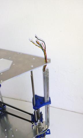
You will need to install at least 13 wires plus one-way thin shielded cable. They go from the bottom to the top of the robot. We have foreseen some pass-through holes near Z linear axis to install them. You will see the holes on both triangles and Top Lead-screw Support parts.
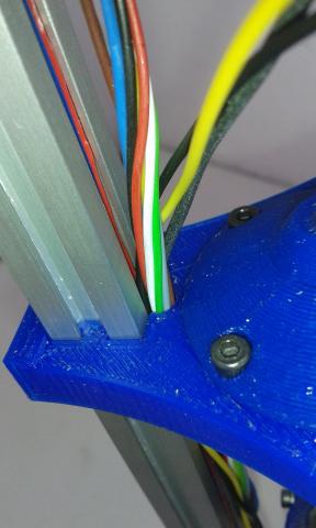
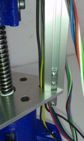
The idea is to insert most wiring in the aluminium extrusion slot but there is not enough placing for all, so some wires have to be installed outside. We suggest you to use a 4-wire flat cable for 3D printers' stepper motors because it will fit well into the extrusion slot.
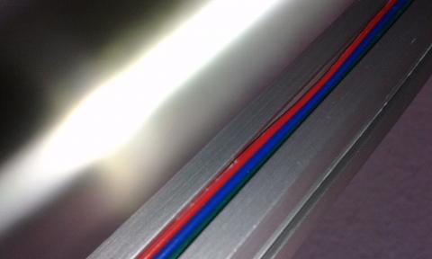
You can use a piece of transparent plastic cable duct and some zip-tie to attach the rest of wires to the column.

For the focus signal, you need a thin 1-core shielded cable. You can use the cable of an earphone or microphone. Flexible ethernet cable wire is fine for the rest of signals because they only carry a few mA.
Grounding and the auto-levelling circuit
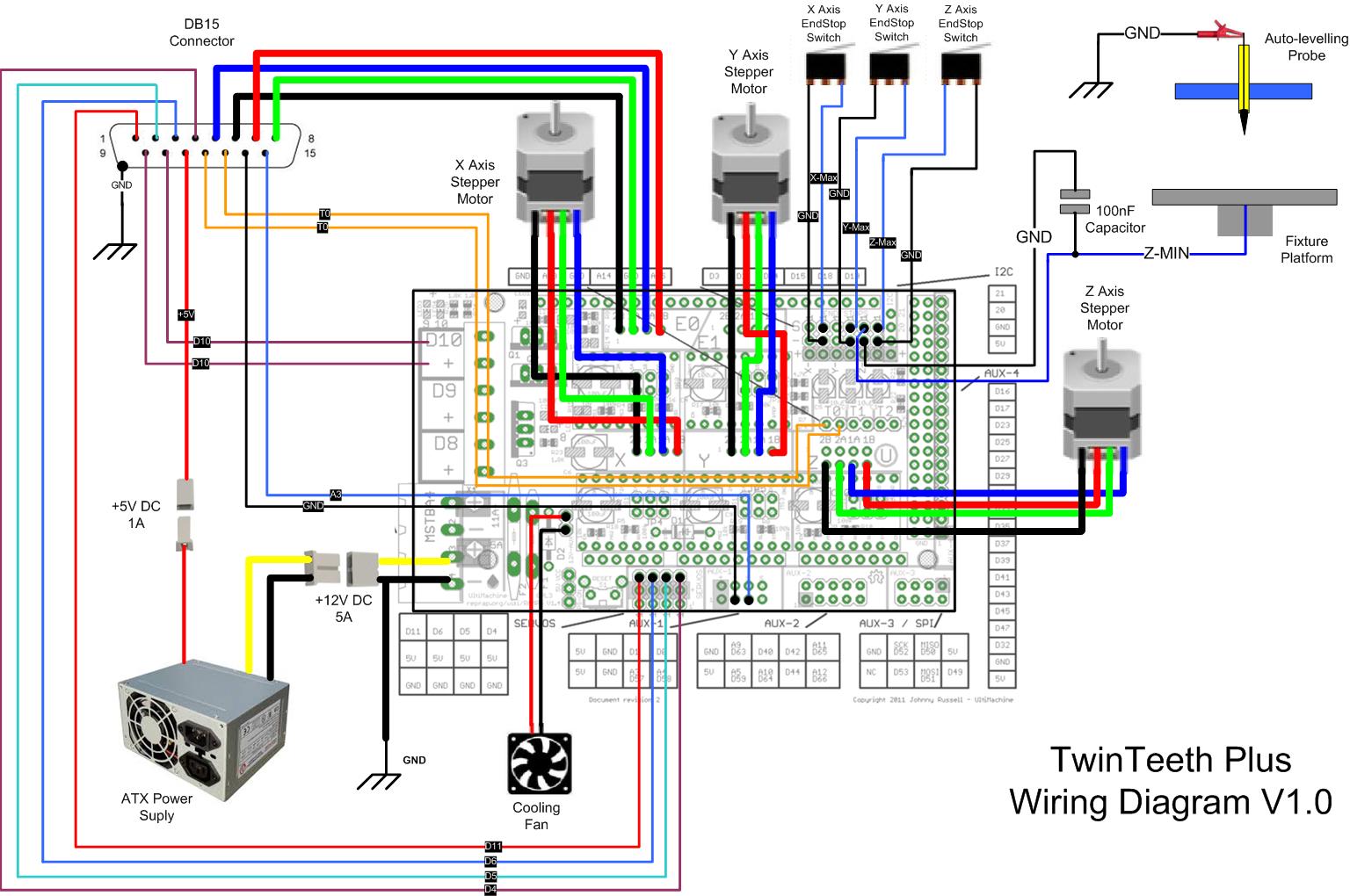
TwinTeeth Plus uses a metal framework, which is connected to GND. We use the framework as digital GND. DB15 connector shield is also connected to GND using a bolt on the top triangle.
We changed the polarity of the auto-leveling circuit as well.
In previous TwinTeeth version, we installed a wire from an Arduino port to the top side of the robot for connecting the auto-levelling probe. The auto-levelling system uses this probe, during the calibration process, to measure the distance from the probe to the bed in several points. With this information, the firmware automatically levels the bed while the robot is moving.
In previous version, the probe was connected to the Z-Min end-stop pin, while the spring cable was connected to GND and to the fixture bed.
As we said, TwinTeeth Plus uses a metal framework connected to GND, so we were a little concern about touching the framework with the clamp closing the circuit. Therefore, we changed the polarity of the circuit and now the probe crocodile clamp wire are connected to GND (via a bolt on the top triangle) and the fixture bed is connected to the Z-Min signal through the spring cable.
You can see this modification on the following diagram.
Installing the Top Triangle
Take the top triangle and put it on the aluminium extrusions. Note that one of the vertexes is different because it has a pass-through hole for the wiring and two M3 holes for installing the DB15 connector. It corresponds to the Z linear axis and has to match with the bottom triangle vertex, which also has the wiring hole.
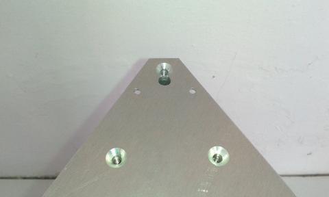
Insert the wires through the wiring hole.
Check that the countersunk holes are pointing up. That is the top side of the triangle.
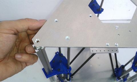
Using three M4x16mm countersunk screws attach one of the vertexes to the column and the steel shafts. Do not tighten the bolts yet, just screw the three bolts little by little, at the same time, and then tighten all together. This is to avoid possible sheet bending.
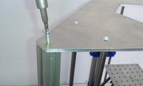
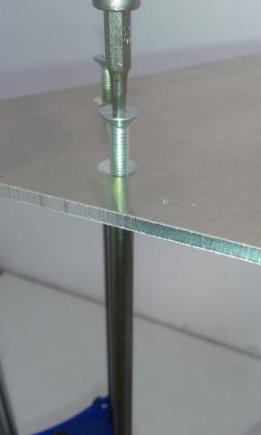
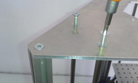
Repeat last operation on the rest of vertexes.
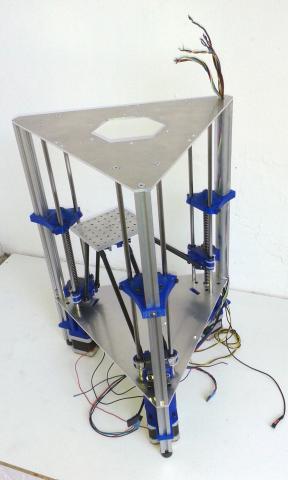
Installing the DB15 Connector
All those wires you have installed carry signals from the Arduino/Ramps to a DB15 connector installed at the top side. The connector is used to plug the ToolHeads.
Next table shows a complete description of the DB15 connector pin out.
| DB15 | ToolHead | Arduino/Ramps | IN/OUT | Signal Name | Description |
|---|---|---|---|---|---|
| 1 | Laser | D11 | OUT | SEL1 | SEL1 and SEL2 turn on/off one of the three laser diodes (UV, Red and IR) |
| 2 | Laser | D5 | OUT | Lens servo | PWM signal for moving the focus lens. |
| 3 | Laser | D6 | OUT | Laser power | PWM signal for controlling the laser diode current (and power) |
| 4 | Laser | D4 | OUT | SEL2 | SEL1 and SEL2 turn on/off one of the three laser diodes (UV, Red and IR) |
| 5 | 3D Printer/Paste Dispenser | E0-1A | OUT | Stepper 1A | Stepper motor coil 1-A. |
| 6 | 3D Printer/Paste Dispenser | E0-2B | OUT | Stepper 2B | Stepper motor coil 2-B. |
| 7 | 3D Printer/Paste Dispenser | E0-1B | OUT | Stepper 1B | Stepper motor coil 1-B. |
| 8 | 3D Printer/Paste Dispenser | E0-2A | OUT | Stepper 2A | Stepper motor coil 2-A. |
| 9 | 3D Printer | D10 | OUT | Heater | Hot-end heater. |
| 10 | 3D Printer | D10 | OUT | Heater | Hot-end heater. |
| 11 | Laser | N/A | N/A | +5V | Direct +5V from PSU. |
| 12 | 3D Printer | T0 | IN | Thermistance | Hot-end thermistance. |
| 13 | 3D Printer | T0 | IN | Thermistance | Hot-end thermistance. |
| 14 | Laser | GND | N/A | GND | Pickup Driver Analog GND (FE cable shield) |
| 15 | Laser | A3 | IN | FE | Focus Error signal line. |
| DB15 Shield | Laser | N/A | N/A | GND1 | Pickup Driver digital GND (direct from PSU) |
Now we are going to install the connector.
Take the male DB15 connector and the DB15 Cover part.
Check that the connector fits well into the cover part and use a cutter to go over the plastic and adapt it till the connector fits properly.
Using the soldering iron, install two M3 nuts in their traps (see next picture). We will use them later to bolt there the connector.
Put the cover on the top triangle and insert the wires through it. Don't bolt it yet.
Cut 10cm of black wire for connecting the DB15 GND shield to the framework. Solder a ring crimp connector on one side of the wire (or make a ring with the own wire) and pass it through the wiring hole. The ring connector is at the bottom side.
Cut approx. 30cm of red wire and solder a ring to it. Insert it through the wiring hole. This will be the auto-levelling wire. Solder the crocodile clamp on the other side.
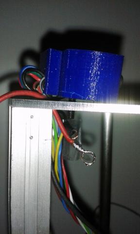
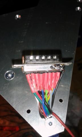
Solder the black cable to the DB15 shield. Solder also the rest of wires to the pins except the auto-levelling red wire. Use heat shrink to insulate the connections.
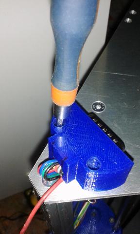
Using two M3x8mm screws, attach the DB15 connector to the cover, and using two M3x10mm screws and two nuts, install the DB15 cover on the triangle. Before screwing one of the nuts, insert the rings of the GND and auto-levelling wires on the bolt. Then insert a washer and then the nut. Tighten both screws and nuts.
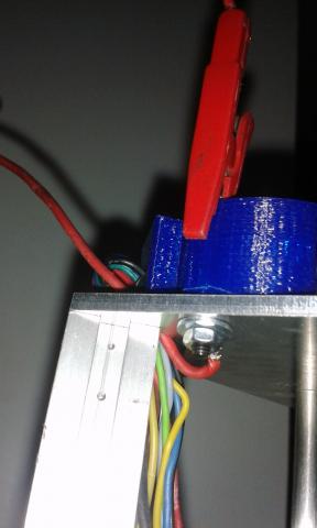
The framework is almost assembled, and looks like the following pictures:
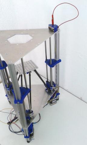
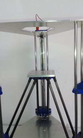
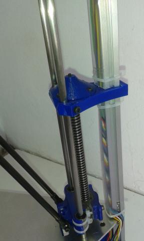
Finally using three M3x16mm bolts and nyloc nuts install the ToolHead Retainer knobs.
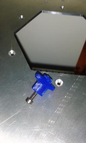
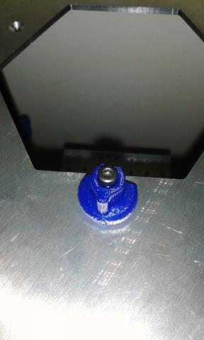
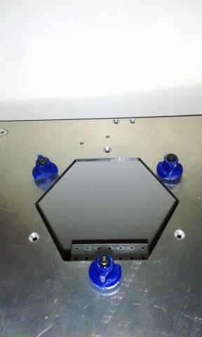
In next chapter you will install the electronics.
Previous chapter Assembly Index Home Next chapter

