TwinTeeth Plus - Installing the Electronics
In this chapter we are going to install the electronics.
TwinTeeth uses an Arduino Mega 2560 and a Ramps 1.4 board which holds the Pololu A4988 Motor Drivers and other electronic circuitry.
This low-cost board was designed for the RepRap 3D printer and now is very popular. Together with the Arduino provide most of the electronics needed by TwinTeeth. Only the Laser Toolhead uses an additional circuit: the Pickup Driver. It has the function to interface the PHR-803T blu-ray pickup and the Arduino. This chapter doesn't cover this circuit because we will describe it later in "Assembling the Laser ToolHead" chapter.
Turn the framework upside down because the electronics is installed at the bottom side.
Installing the end-stop micro-switches
If you did not install the end-stop switches before, then now is the time to do it.
TwinTeeh Plus was designed to use common subminuature DB series micro-switches with straight terminals and no auxiliary actuator. You can use any of this series because the max. current which will pass through it will be only some mA and a potential tension of 5V.
End-stop switches usually have three terminals. They are marked C (common), NC (normally closed) and NO (normally open).
The terminal at the centre of the switch is usually the NO (normally open) terminal. We don't use it.
Solder two wires on the NC and C terminals (see next picture) and using a cutter or a file go into the end-stop plastic housing of each vertex till the end-stop fits well into it.
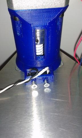
Then using two M2 or M2.5 metal-sheet screws, attach the end-stop switch into the housing through the two holes foreseen on the plastic.
The switch has to be levelled with the top surface of the triangle and the tiny actuator button standing out of it (see next picture). The actuator button must be centred between the 6mm axis.
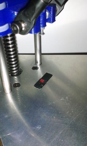
Turning the lead-screw by hand, move the carriage to the bottom position and check that the end-stop screw hits the actuator properly.
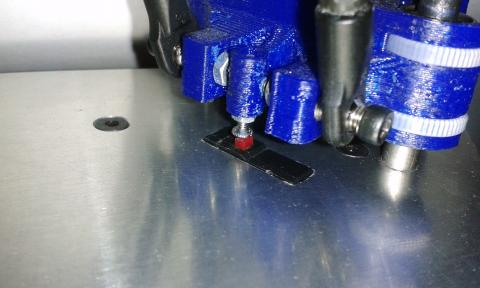
Repeat these steps with the other end-stop switches.
Installing the Arduino and the Ramps
We are going to attach the Arduino Mega to the bottom triangle. Before do it, insert the spring cable on the 6mm hole at the centre of the triangle because later will be difficult to do it.
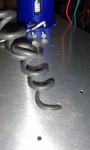
Cut also a piece of AWG18 or AWG22 black wire for the main GND framework connection. There is a hole under the Arduino to connect this wire. Use a crimp ring terminal (or make it with the wire) and bolt the ring on the framework using a M3x8mm countersunk bolt, a washer and a nut.
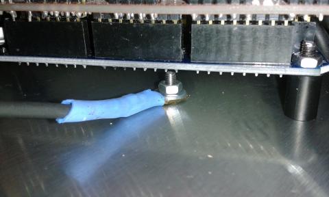
Use four M3x20mm countersunk screws and four PCB spacers for installing the Arduino on the bottom side of the triangle.
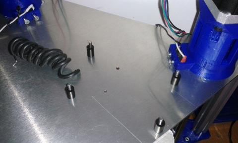
Put the Arduino on the PCB spacers and insert the bolts on the board installation holes.
Arduino board installation holes are M3 size but it's difficult (or almost impossible) to attach it using M3 nuts because there is not place for them. So we suggest you to use four M3 nylon nuts and cut a little two of them, to fit the nuts in so narrow space (see next picture).
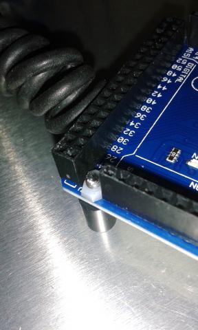
Take the Ramps board and solder two male pins on the 12V-Aux pin holes (see next picture). Most Ramps boards come without these pins. Later we will connect there the cooling fan (see wiring diagram).
Check that all the microstep jumpers are installed in all axes. TwinTeeth Plus uses 1/16 microstepping.
Install the Ramps on the Arduino. Take care to insert all the pins at the same time.
Find the stepper motor drivers.
You will need three drivers for the X,Y,Z motors and an additional one which is shared by the 3D Extruder motor and the Paste Dispenser motor (in case you want to use those ToolHeads)
Before installing the drivers, paste the small Alu. radiator on the A4988 ICs.
Then Insert the drivers in the X, Y, Z positions on the Ramps. Insert also the fourth driver in the E0 position (if you want it).
Warning: take care when installing the drivers on the Ramps because if you install them incorrectly you will destroy them. You will also destroy them if you connect/disconnect the motors while the power is on.
If you look at the board with the yellow fuses on your left, then the correct position of the drivers is with its tiny potentiometer pointing to your right (see next picture).
Now solder on the bottom end of the wires the female pin connectors needed to connect the wiring to the Ramps.
You will need:
- 4-pin female connector for the E0 Stepper Motor wires (see below Wiring the Stepper Motors)
- 4-pin female connector for the D11,D6,D5,D4 Pickup Driver signals.
- 2-pin female connector for the shielded cable A3/GND (FE signal)
- 2-pin female connector for the T0 wires (Hot-end thermistance)
Solder also:
- 1-pin connector to the +5V power supply line for the Pickup Driver
- 2-pin female connector to the cooling fan. This fan is optional but we suggest to use it for cooling the stepper motor drivers.
Adjust the wire length of the end-stop switches and solder also a 2-pin female connector to each of them.
We suggest you to use heat shrink tube and insulate all those connections.
You don't need to solder any connector to the D10 wires (Heater) because they will be installed into the D10 clamp connector of the Ramps.
Wiring the stepper motors
The three X,Y,Z NEMA 17 motors usually come with four wires long enough to connect them directly to the Ramps. Otherwise you will need to increase their length with a joint.
Check the stepper motor wiring configuration to see that the colours of the wires correspond with the coils of the motor and with the pins 2B,2A,1A,1B on the Ramps. Each stepper motor manufacturer uses different wiring colours and sometimes it is confusing.
We recommend to use Wantai 42BYGHW609 stepper motors with the following wiring colours:
Solder a 4-pin female connector to the four motor wires of each motor in the correct order.
Connecting the Wiring
Once all the wiring is ready you can connect it to the Ramps.
First, connect the X,Y,Z stepper motor cables. Make sure to insert them in the correct pins and position: 2B,2A,1A,1B.
After that, connect the end-stops switches. RAMPS has six connectors for end-stops, max .and min. each for X, Y and Z axis. The end-stop pins are grouped on the top right of RAMPS and are clearly marked end-stops, X-, Y- and Z- (these are the min. end-stops, the equivalent max. end-stops pins aren’t marked and are between/after these). Each has three pins marked S, -, +.
Most CNC and 3D printer machines use the min. end-stops for homing but TwinTeeth Plus is an inverted delta robot and it uses the max. end-stop connectors for it.
Connect now each end-stop to the max end-stop connector of each axis. The switches are connected to the S and - pins.
Warning: If you connect the end-stops incorrectly you will cause a short-circuit in the Arduino. This is easily done if you plug the 2-pin plug in - and + pins instead of S and -.
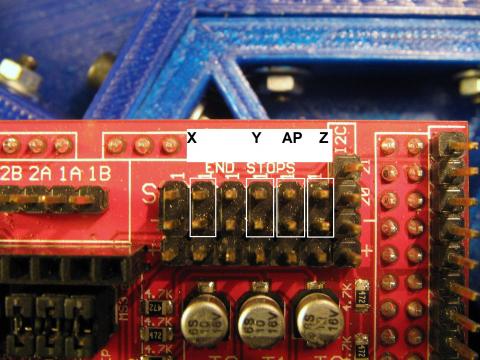
AP in last picture means Auto-Levelling Probe. We will connect it later.
Connect also the FE shielded cable in its position (GND and A3) on the Aux-1 pin area.
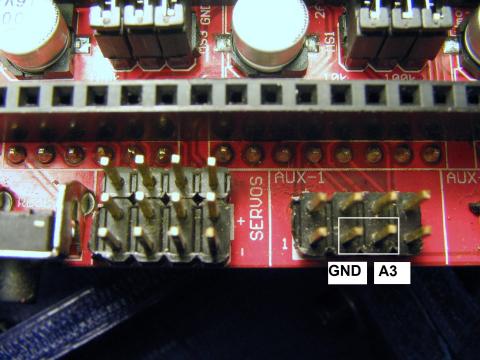
And connect the D11-D4 wires of the laser ToolHead to the servos pin area.

Connect the thermistor wires to the T0 pins.
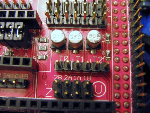
Clamp the two D10 wires of the hot-end heater to the D10 connector of the Ramps.
If you are going to use the cooling fan (optional), find a position to install it and connect it also to the Ramps.
Finally check twice that all the wiring is correctly connected. This is important because if there is anything wrong you can destroy the electronics.

Wiring the Power Suply
The best power supply for TwinTeeth is probably a PC ATX power supply. TwinTeeth Plus uses two different voltages: +12V and +5V and ATX power supplies provide both of them and enough current for all the electronics and motors.
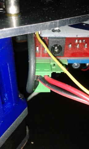
The +12V line is used to power the Ramps, Arduino, Stepper Motors, Hot-end, etc. You have to connect this wire and the GND to the 5A-12V green clamp connector of the Ramp (see next picture). Connect also there the GND black wire you bolt to the framework under the Arduino board.
The +5V line is used to power the Pickup Driver circuit of the Laser Toolhead. This line comes directly from the power supply. Don't power this circuit from the Arduino because you could create an overcurrent on the pins and destroy it. Also the Arduino is very noisy and it can induce that noise on the Pickup Driver which is very sensible to it.
Take care with the polarity of the power supply wires.
Note that there are two GND signals on the DB15 connector: one analog GND signal comes from the Arduino through the shielded FE cable. The other one (digital GND) comes directly from the power supply to the framework and finally it is connected to the DB15 shield. It's important to maintain these two GND lines in order to isolate the Pickup Driver from electric noise.
You will need to adapt the PC ATX power supply before using it with TwinTeeth. Take a look at this RepRap Power Suppy Tutorial where you will find useful information about how to do it. Note that TwinTeeth will need an additional +5V line (red). The RepRap doesn't use it.
Don't use the +5V standby line (purple) instead of the +5V (red) because it is always on and only provides 10mA of current. Any of the red wires will be OK.
We recommend you to use a 3-ways connector (+12V, GND, +5V) to easily connect/disconnect the power supply to TwinTeeth Plus.
Warning: Don't connect the power supply yet, not until you check that the drivers are correctly installed, the wiring is OK and the firmware uploaded.
Assembling the Auto-Levelling Probe
As we see in last chapter the auto-levelling system uses a probe during the calibration process to measure the distance from the probe tip to the bed. You already installed the probe wire and the crocodile clamp which are connected to the top GND bolt and now we are going to install the rest of the circuit.
You will need the following materials:
- 1 x spring telephone cord or similar
- 1 x one-wire male/female terminal
- 1 x two-wires female pin connector
- 1 x 100nF ceramic capacitor
- 1 x crocodrille clamp
First solder the one-wire male connector to the top end of the spring wire. Remember that we already soldered the female part to the fixture platform bolt.
Connect the male connector to the fixture platform female connector.
Solder the 2-pin female connector to the other end of the wires. Don't forget to solder between the spring cable and the other pin (GND) a 100nF ceramic capacitor. This is to avoid spurious signalling.
Connect the spring cable/capacitor connector to the S (signal) pin of Z-MIn and the GND pin (AP position in next picture).

As we already saw, the probe closes a circuit when touching the aluminium fixture bed. It is used by the robot to take some “reference points” and know how much has to adjust the bed, for levelling it while moving.
Now we are going to assemble the probe. You will need the following materials:
- 1 x marker Pen Hexagon
- 1 x 9.5mm (OD) used marker pen with no ink
- 1 x metal conductive tip
- 1 x piece of 1mm cooper wire (70mm)
- 1 x drop of Cyanoacrylate
For the conductive tip you can use: a tiny connector pin, a sharp multimeter test lead, a sharp cooper tip or something similar. We will solder a wire to it, so it has to be made with an easy-soldering metal.
First check that the marker pen fits well into the hexagon hole and use a 9.5mm drill bit to clear the hole if needed.
Using a metal saw cut the marker pen at approx. 45-50mm from the tip.
Then using pliers remove the ink cartridge and the tip. Clean with alcohol or acetone the rests of ink if needed.
Solder the wire to the conductive pin and introduce it through the marker tip hole. Make a loop on the other side of the wire to attach the crocodile clip.
Finally glue the tip to the marker with a drop of cyanoacrylate.
Check that it slides well through the hexagon hole.
The Auto-levelling Probe is ready.
It is very easy to use it: just clamp the crocodile clip to the bended wire and run the auto-levelling process. We will do it later.
You can also clamp the crocodile clamp to any conductive tool tip if you want to. For example a drill bit installed in a mini-rotary tool.
Next tutorial chapters are shared between TwinTeeth Basic and TwinTeeth Plus.
Previous chapter Assembly Index Home Next chapter
