Dispensing solder paste
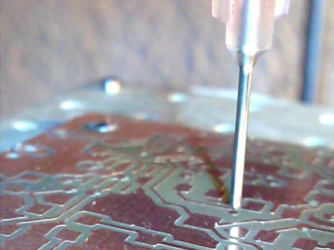
In this chapter we will cover the process of dispensing solder paste on SMD pads using the Paste Dispenser ToolHead.
The process consists on the following steps:
- Generate the CAM files
- Install the Dispenser Toolhead
- Set the program zero
- Dispense the paste
We will use as an example the schematic and Eagle board design we used for photoengraving the PCB with the Laser Toolhead.
Run Eagle Cadsoft and open the LaserDriver project you create for photoengraving.
Generating the CAM files
The Paste Dispenser ToolHead use g-code as CAM file format. We developed a special Eagle's ULP to easily generate g-code files from the board design. You already installed it and use it in previous chapters. (See Installing Eagle's ULPs for TwinTeeth section on the software Installation chapter)
You have to switch to the board view to run the ULP. Select the top layer because we will dispense the paste on the top side.
User Language Programs are executed using the Run command. Click on the icon.
A file selector will appear. Go to the directory where you installed the zip file and open twinteeth.ulp file.
You will see the TwinTeeth ULP window, similar to this:
This window has two tabs with the labels: Drill Tool and Paste Dispenser Tool. The first one contains the Drilling ToolHead configuration panel and the second one the Paste Dispenser panel. When configured, you can generate the files clicking on the "Save G-code button". Files usually are saved on the project directory.
We will describe now how to configure the Paste Dispenser Panel. Click on that tab.
The paste dispensing configuration panel has several areas: the generation area, the flow rate area, the z axis control area and the feed rate area.
You can only dispense paste on the top side of the PCB so the Generation Area only allows you to activate or deactivate the generation of the g-code file of that side.
The flow rate area allows you to configure flow speed of the solder paste. You will see there the following fields:
- Extruder Rate - This is the speed of the dispenser stepper motor in mm/min. A range between 195-205 is ok.
- Min. dispensing time - It's the minimum dispensing time in milliseconds that the dispenser will extrude paste.
- Dispensing time per mm2 - Allows you to dispense more paste in big pads and less in small pads.
- Retraction time - It is the time in milliseconds that the motor will run in reverse direction. It's useful to stop dispensing paste while the robot is going from one pad to the next one.
The Z axis control area allows you to manage the behaviour of the Z axis. You will see there the following fields:
- Z High - The highest Z axis position in mm when starting dispensing.
- Z up - The Z axis position in mm when moving from one pad to the next.
- Z dispensing- The Z axis position in mm where the dispenser needle will start to dispense paste.
- Dispensing Dwell - It is the time in ms that the robot will pause after dispensing on one pad.
Finally you will see the feed rate area which allows you to set the X,Y and Z axis feed rates in mm/min.
Now configure the parameters on your board and then click on the Save g-code button.
The ULP will generate only a g-code file. The name of the file will be similar to this one:
- twinteeth-laserdriver.brd.paste.gcode
You will find them at the Eagles's project directory.
Our suggestions are:
- Use the appropriate needle diameter. 20-22 gauge should be ok.
- Maintain the pressure applied to the syringe at a minimum. This kind of dispensers has hysteresis. It means that the paste continues flowing after the motor stops.
- Use some retraction time to avoid hysteresis, but not more than dispensing time.
- Z dispensing parameter determines the gap between the needle and the PCB surface and affect the shape of the dot dispensed. If the clearance is too little the dot tends to be flattened.
- Take out the solder paste from the refrigerator 3-4 hours before use it. Flow rate depends also on paste viscosity and paste viscosity on its temperature.
Installing the Paste Dispenser ToolHead
In this section we are going to prepare and install the Paste Dispenser ToolHead.
Find the dispenser, fill the syringe with paste and install it on the hexagon as we described in Assembling the Solder Paste Dispenser ToolHead chapter.
Check that the printer is disconnected. Install the ToolHead on TwinTeeth, lock it with the retainer bolts and connect the DB15 cable.
Put the PCB on the platform and turn the power supply on.
Run the camera application and adjust the camera pointing to the needle. Focus the objective if needed and turn the LEDs on.
Setting the program zero
Run TwinTeethMC and connect to the robot.
Click on the Paste Dispenser tab.
Click on the Calibrate button to show the calibration controls.
Set the Z min slider to zero because the paste dispenser does not need to go beyond that point.
Click on the Reset tool button to initialize the tool configuration and click on Home.
Then using the Z control move the platform up till the needle almost touches the PCB surface. Then move the X and Y axis till the needle point to the circle you draw at the Eagle's board design. As we already see when drilling, after the etching process the circle is a small isolated pad on the cooper foil.
Carefully move the Z axis till the needle touches the PCB surface on the center pad, in a similar way you did when drilling.

Then click on the Set Program Zero button to set the current location as the coordinate origin.
Click again on the Calibrate button to hide the calibration controls and home the platform.
To check that it is well calibrated click on the "Goto Zero" button to go to that position. The platform will move up and stop just when the needle touches the PCB surface.
The Paste Dispensing ToolHead is ready.
Dispensing the paste
In this section we will run the job.
Before that, purge the sryringe a little to remove the air in the needle and facilitate the releasing of the paste. You can do it using the auxiliary controls. Be patient and don't dispense too much at the same time. The paste has to start to flow very slowly. Otherwise you probably will have to use the reverse button to stop the flowing.
The flow speed has a very narrow margin: approx. 195-208 mm/min. Out of that range the motor will not move.

Click on the Load File button and load the g-code file. You will see a representation of the tool path at the Simulation Area. Each line corresponds to a platform movement and the square pads to a dispensing action.
Using a piece of paper clean the needle point of excess of solder paste and then click on the Run Button to execute the job.
The robot will start to dispense the paste. You will see the evolution of the job at the simulation area and through the camera.
When the job is finish home the platform. The board is ready!
We will see in next chapter how to 3D print with TwinTeeth.
Previous chapter Use it Index Home Next chapter
